Liquid cooling for AI is the operating standard for any rack that crosses the 50 kW threshold in 2026. The phrase describes any thermal architecture that pulls heat off accelerators with a working fluid instead of bulk air. As a result, the cooling loop reaches the silicon, not the room. Uptime Institute’s Global Data Center Survey reports that direct liquid cooling adoption has roughly tripled across high-density operators since 2022. The reason is simple. Air cannot move the watts that modern accelerators emit.
The shift is now the dominant design signal across new AI campuses. IEA Electricity 2026 reports AI as the fastest-growing electricity load class in advanced economies. Meanwhile, ASHRAE TC 9.9 datacom guidance formalized liquid-class envelopes that operators now treat as default. In addition, IEEE Spectrum reporting on direct-to-chip deployments documents pilot-to-production transitions at hyperscale. Therefore, every new high-density build now begins with a liquid plan, not an air plan.
The takeaway up front. Air cooling optimizes for the building. Cloud GPU rental optimizes for the cloud vendor. By contrast, a closed-loop liquid stack optimizes for the buyer who funds the entire campus. SAVRN designed its sovereign architecture around that decision. SAVRN is the operator of an off-grid sovereign AI infrastructure campus model, with current developments underway in California, Texas, Colorado, Nebraska, Panama, and Barbados. Also, SAVRN owns its power, compute, and closed-loop liquid cooling, and deploys in 6 to 12 months versus the 24 to 48 month industry standard. This guide walks through the physics, the four architectures, the water math, the supply chain, the economics, and the SAVRN approach.
Why liquid cooling for AI replaces air at the 50 kW rack
The rack has outgrown the room. Three signals confirm the shift. First, accelerator thermal design power has roughly doubled across three generations of compute. Second, rack-level power has crossed 50 kW for mainstream AI training and inference. Third, hyperscalers have published direct-to-chip designs that no longer keep air as a backup option. Therefore, the air era is closing on the AI side of the hall.
Air hits a hard physics ceiling around 30 kW per rack
Air carries roughly 1,000 times less heat per unit volume than water. Consequently, hot aisle and cold aisle designs run out of headroom near 30 to 35 kW per rack. Beyond that, the fan power required grows non-linearly. So, the IT load wastes energy to push more air faster. Meanwhile, the chip junction temperature still creeps up. In short, air capacity per dollar collapses.
The math is simple. A modern AI rack at 100 kW would need fan loads that approach 10 to 15% of total IT power if cooled by air alone. By contrast, a liquid loop pulls 70 to 95% of heat directly at the chip, with much smaller pump loads. As a result, the fan tax disappears. Also, the rack power that the building must reject in air drops sharply.
AI rack power has crossed the air-to-liquid threshold
The 2024 to 2026 step in accelerator power is the inflection point. Earlier accelerator generations ran at roughly 300 watt TDP. Current and near-term parts now reach the 700 to 1,000 watt class per device. As a result, rack densities of 80 to 130 kW have become routine for inference fleets. Next-generation systems on the published industry roadmap target densities well above 200 kW per rack. In short, the watts no longer fit through air.
The shift is broad, not edge case. Uptime Institute survey data shows roughly one in three operators now plans liquid for new builds. Meanwhile, large public deployments from Google’s TPU pod program and Microsoft’s hyperscale fleet confirm that production-grade liquid loops scale to thousands of racks. Therefore, rack-level liquid is the default for any new high-density build.
Why the air-versus-liquid debate is over for new AI factories
The economics of new construction tilt decisively to liquid. Operators get higher compute per square foot, lower PUE, and a smaller HVAC envelope. In addition, the warranty profiles of new accelerator platforms now assume direct-to-chip in the reference design. Consequently, choosing air for a new high-density build trades short-term familiarity for long-term cost and a smaller addressable workload set. So, the choice has narrowed to which liquid class to pick, not whether to use liquid.
The four liquid cooling for AI architectures operators compare in 2026
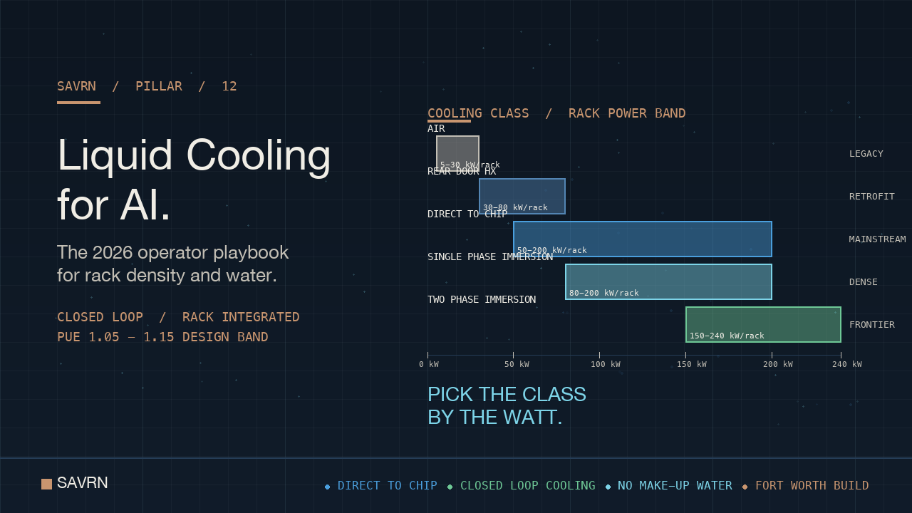
Four architectures dominate the 2026 market. Each maps to a rack power band. In addition, each carries its own capex, retrofit path, and operating regime. Choosing the right class first prevents costly rework later.
Direct-to-chip cold plates anchor the mainstream tier of liquid cooling for AI
Direct-to-chip places a cold plate on the hottest devices, typically the GPU and CPU dies. Coolant flows through micro-channels, picks up heat, and returns to a coolant distribution unit. The CDU exchanges heat with the facility loop. As a result, 70 to 80% of total rack heat moves to liquid at the device interface. Meanwhile, the remaining heat from memory, NICs, and PSUs still exits via rear-rack air.
The class fits the 50 to 200 kW rack band cleanly. Vendors ship complete manifold and quick-disconnect kits. Therefore, integration risk is low for new pods. In addition, ASHRAE liquid classes W17 to W32 specify warm-water operating points, so chillers are often unnecessary. So, capex falls, and the climate envelope of viable sites widens. In short, direct-to-chip cold plates have become the default entry into rack-level cooling.
Rear-door heat exchangers retrofit existing halls for liquid cooling for AI
Rear-door heat exchangers swap the rear panel of the rack for a finned coil. Coolant in the coil absorbs the warm exhaust before it returns to the room. As a result, room-level cooling load drops. Meanwhile, no plumbing penetrates the IT chassis. In short, the rear door is the retrofit-friendly class.
The class fits the 30 to 80 kW rack band well. Operators add capacity to legacy halls without ripping out raised floor or CRAC units. Therefore, brownfield AI sites use rear doors as a transition layer. However, the class hits a ceiling. As rack power climbs past 100 kW, rear doors cannot move the heat. So, the path forward is to graduate to direct-to-chip or immersion.
Single-phase immersion gives liquid cooling for AI a dense baseline
Single-phase immersion submerges entire servers in a dielectric fluid. The fluid stays liquid the entire time. A pump moves warm fluid to a heat exchanger, which then rejects to the facility loop. As a result, every component cools at once. Also, fans and most internal airflow paths disappear. Consequently, the IT energy budget drops by 10 to 20% on a like-for-like basis.
The class fits the 80 to 200 kW rack band, expressed as horizontal tanks. Operators give up vertical floor density in exchange for thermal density. Meanwhile, tank designs now ship as standard SKUs with quick-disconnect interfaces. Therefore, integration risk is moderate, not exotic. In addition, the fluid itself, often a synthetic hydrocarbon, is dielectric and non-toxic by design.
Two-phase immersion pushes liquid cooling for AI past 200 kW per rack
Two-phase immersion uses a low-boiling-point dielectric. The fluid boils at the chip surface and condenses on a cold plate at the top of the tank. As a result, heat moves via the latent heat of vaporization, which is far higher than sensible heat. Therefore, two-phase handles the highest rack power bands on the published roadmap.
The class fits the highest density tier, often 200 kW and above per tank. In short, two-phase covers the next-generation AI rack densities the industry has telegraphed. However, the supply chain for low-GWP fluorinated fluids is still consolidating. Meanwhile, regulatory scrutiny of perfluorinated chemistries adds risk. So, operators weigh density against fluid-supply continuity.
The water question that decides liquid cooling for AI siting
Water is the most misunderstood variable in the cooling discussion. The fluid inside the rack is small, often a few hundred gallons per pod. By contrast, the facility loop and the rejection plant can consume far more. As a result, two campuses with identical IT can have very different water footprints. Therefore, siting starts with the rejection class.
Closed-loop systems decouple liquid cooling for AI from local water budgets
Closed-loop dry coolers and adiabatic systems can run with near-zero make-up water. The campus loop circulates the same fluid for years. As a result, the facility detaches from municipal water supply. Meanwhile, the campus accepts a small efficiency penalty on the hottest days. In short, closed-loop trades a few percentage points of PUE for water resilience.
SAVRN ships closed-loop as the default cooling class. The campus is engineered to operate without make-up water. As a result, sites in dry geographies remain viable. Therefore, the water permitting path that has stalled many 2024 and 2025 builds drops out of the SAVRN site map. For a deeper treatment of the water question, see SAVRN’s 49 billion gallon mirage.
Evaporative towers still anchor most legacy halls
Evaporative cooling rejects heat by evaporating water. The water demand is large, often 1 to 4 gallons per kWh of IT load at peak. As a result, a 100 MW hall on evaporative rejection can consume hundreds of millions of gallons each year. Meanwhile, drought-prone geographies treat that draw as a public liability. Therefore, evaporative is now a regulatory risk vector, not just an engineering one.
The retrofit answer is to graduate legacy halls to closed-loop where possible. However, the heat rejection plant is expensive to replace mid-life. In short, evaporative continues to anchor the install base while new builds move to closed-loop by default.
Why the water footprint of a liquid-cooled rack is smaller than the headlines
Public discourse often confuses chip-side liquid with facility-side water. The chip-side fluid is sealed. The facility side is what consumes water, and only if the rejection class uses evaporation. As a result, a closed-loop campus with direct-to-chip racks can be a net water saver versus a comparable air-cooled hall with evaporative towers. In short, the choice of rejection class matters more than the choice of internal loop.
The economics of liquid cooling for AI in 2026
Operators evaluate three cost surfaces. First, the per-rack capex of the cooling stack. Second, the PUE delta and the electricity bill that follows. Third, the maintenance overhead and skilled labor profile. The picture is favorable for liquid on new builds. By contrast, the picture for retrofits is mixed and case-specific.
Per-rack capex bands for liquid cooling for AI
Direct-to-chip systems land in the lowest capex band. Manifold, CDU, and quick-disconnect kits add a modest premium over an equivalent air rack. Rear-door retrofits sit in a similar band, with the CDU sized for fewer racks. By contrast, single-phase immersion runs higher per slot, in part because the tank is the rack. Two-phase immersion sits at the top of the band, driven by fluid cost.
The capex picture inverts when measured per unit of compute. A 100 kW direct-to-chip rack often delivers more compute per square foot than two air racks combined. As a result, the building, civil, and land share of total project cost drops. Therefore, the cooling premium frequently pays back in the first refresh cycle.
PUE and the electricity bill
Legacy air halls cluster in the 1.4 to 1.6 PUE range. New direct-to-chip builds frequently report 1.05 to 1.15. The difference compounds. As a result, a 100 MW campus saves 30 to 60 GWh per year on the non-IT side. Meanwhile, the IT side itself draws less, because fans inside the chassis no longer spin at the same rate. In short, the cooling architecture is a top-line lever on the energy bill.
The savings get sharper when paired with on-site power. For a deeper treatment of how on-site generation pairs with closed-loop cooling, see SAVRN’s behind the meter AI power guide. Also see the deployment-economics view in SAVRN’s tokens per watt per dollar reference.
Maintenance and the skilled labor profile
Liquid systems require a different operator skillset. Technicians work with quick-disconnect fittings, manifold pressure, and leak detection. As a result, operations teams hire or train for mechanical fluency, not just electrical. Meanwhile, the fluid itself needs periodic conditioning, sampling, and replenishment. So, the operations manual gets thicker, but the failure modes are well understood.
The labor profile favors operators who control the full stack. Therefore, in-house mechanical teams scale better than outsourced ones. In short, an integrated operator runs liquid cooling for AI more efficiently than a tenant in a colocation environment.
The supply chain that powers liquid cooling for AI
The vendor ecosystem matured fast between 2023 and 2026. As a result, integration risk has dropped sharply. However, lead times on specific subsystems remain a bottleneck. Operators that lock supply early avoid the squeeze.
CDU vendors and capacity classes
The coolant distribution unit is the heart of the rack-to-facility loop. Vendor capacity classes run from roughly 100 kW to over 2 MW per CDU. As a result, operators size CDUs to row or pod, not to individual racks. Also, redundancy is achieved at the manifold and pump level, not by oversizing single units. In short, the CDU is now a commodity-class building block in the rack-level cooling market.
Manifolds and quick disconnect interfaces
Manifolds and quick-disconnect couplings define the operator experience. Good interfaces seal under pressure, prevent drip on detach, and survive thousands of cycles. As a result, the vendor community converged on a small set of dry-break standards. Meanwhile, hyperscalers publish their interface specs through Open Compute Project channels, which has pulled the industry toward shared geometries.
Coolant and dielectric fluid availability
Water-glycol mixes anchor direct-to-chip and rear-door classes. Supply is plentiful. By contrast, single-phase immersion fluids ship from a smaller vendor set. Two-phase fluids are the supply pinch point. As a result, fluid sourcing affects the architecture decision, not just the engineering. In short, supply continuity is a first-class design input for immersion.
How SAVRN treats liquid cooling for AI as day-one architecture
SAVRN designed its campus model around the integrated stack, not around retrofit. The cooling architecture sits next to the power generation and the compute pod in the same engineering brief. As a result, the campus avoids the staged-upgrade penalty that legacy halls now face. Therefore, the SAVRN approach is a clean-sheet view of liquid cooling for AI, not a patch on an older design.
Intelliflex integrated manufacturing builds the cooling envelope on the same line as the compute pod
Intelliflex, the SAVRN integrated manufacturing arm in Fort Worth, ships compute pods with the rack-level cooling already integrated. The factory bench tests the manifold, the CDU, and the pod together. As a result, field commissioning shortens to a connect-and-charge step. Meanwhile, the Intelliflex Customer Experience Center in Fort Worth is set up for hands-on inspection of the rack-level architecture. In short, the cooling stack ships from the same line as the compute. Learn more about the model on the SAVRN Intelliflex page.
Pairing closed-loop generation with closed-loop heat rejection
SAVRN owns both the power generation stack and the cooling stack. Closed-loop generation and closed-loop cooling share design intent. Therefore, the campus runs without make-up water and without grid intercon-dependence. As a result, the site map opens to dry geographies and to sites that the grid queue would otherwise foreclose. For more detail, see SAVRN sovereign AI infrastructure.
A 6 to 12 month commissioning window for liquid cooling for AI
The industry standard runs 24 to 48 months from site to first token. By contrast, SAVRN compresses that to 6 to 12 months. The cooling stack is the keystone. As a result, the pod arrives pre-piped, pre-tested, and ready to charge. Meanwhile, the on-site power plant ramps in parallel. For the full timeline, see SAVRN’s AI infrastructure deployment timeline.
Operator decision framework for liquid cooling for AI in 2026
The right cooling class is the one that matches the buyer’s compute roadmap, not the one with the lowest sticker. Operators that pick the class for today’s racks pay twice when next year’s accelerators arrive. By contrast, operators that pick the class for the rack power band they expect over the next three refreshes pay once. So, the framework starts with the future rack and works backward.
Match the cooling class to the rack power band
Racks under 50 kW can still run on air. The 30 to 80 kW band is the natural slot for rear-door retrofits. Direct-to-chip dominates the 50 to 200 kW mainstream. Single-phase immersion fits where horizontal layouts work in the 80 to 200 kW range. At the highest density tier, two-phase becomes the relevant option. So, the class follows the watts.
Plan for hardware refresh and coolant retirement
Accelerator generations refresh every 18 to 24 months. The cooling stack often outlives several refreshes. As a result, the manifold and CDU choice must accommodate hotter, denser parts a few years out. In addition, coolant retirement and recharge cycles need a service plan from day one. So, the operator picks a vendor with a long-term fluid supply and service contract, not a short-term price.
Instrumentation, leak detection, and observability
Liquid systems demand telemetry. Flow, pressure, temperature, leak presence, and conductivity all matter. As a result, the rack and row become rich data sources. Operators that wire that telemetry into the same observability stack as the compute see the failure modes early. Meanwhile, teams that treat cooling as a black box pay in unplanned downtime. In short, observability is non-negotiable on a liquid stack.
The 2030 outlook for liquid cooling for AI
The cooling market is growing faster than the compute market it serves. Industry analyst tracking from Dell’Oro Group projects multi-year double-digit growth in the data center thermal segment. Meanwhile, Reuters reporting on AI power demand ties cooling spend directly to accelerator shipments. So, the outlook is a steeper adoption curve, not a plateau.
Three structural shifts will define the next four years. First, direct-to-chip will become a commodity that ships pre-piped from the OEM. Second, closed-loop heat rejection will become the regulatory default, especially in dry geographies. Third, two-phase will move from boutique to mainstream as fluid supply stabilizes. As a result, the liquid stack becomes the unambiguous standard for the AI factory class.
The buyer who locks integrated capacity now avoids the squeeze later. Therefore, the decision window is short. Also, the operators who treat cooling as a design-time variable, not a procurement detail, will define the next generation of AI campuses. For context on the broader build-versus-buy choice that frames this question, see SAVRN’s build vs buy AI infrastructure framework.
Three policy threads will also shape adoption. First, state water rules in dry geographies tighten each year, which pulls more builds toward closed-loop. Second, utility tariff design now penalizes peakier loads, which gives liquid an edge by lowering fan-driven load swings. Third, federal energy-efficiency mandates already cite warm-water operation as a best practice. As a result, the policy gradient reinforces the engineering one. So, the buyer who treats cooling as a strategic choice gets a regulatory tailwind, not just a thermal one.
Frequently asked questions about liquid cooling for AI
What is liquid cooling for AI and how does it work?
Liquid cooling for AI moves heat off accelerators with a working fluid instead of bulk air. A cold plate, a sealed loop, or an immersion tank carries the heat to a coolant distribution unit. The CDU then exchanges heat with the facility loop. As a result, the cooling reaches the silicon, not the room. The architecture supports rack densities far above what air can handle.
At what rack power band should an operator switch from air to liquid?
Air starts to fail near 30 kW per rack. By 50 kW, liquid is the practical default. Beyond 80 kW, air is no longer a serious option for new builds. So, operators planning sub-30 kW racks can still use air. Everyone else now plans the liquid class from the start. The threshold is the watt, not the brand of accelerator.
Does liquid cooling for AI use more water than air cooling?
Not necessarily, and often the opposite. The fluid inside the rack is sealed and modest in volume. The water draw comes from the heat rejection plant at the facility level. A closed-loop dry cooler can run with near-zero make-up water. Therefore, a closed-loop liquid campus can be a net water saver compared with an air-cooled hall using evaporative towers.
What is a coolant distribution unit?
A coolant distribution unit, or CDU, sits between the rack-side loop and the facility-side loop. It pumps coolant, filters it, monitors flow and pressure, and exchanges heat across an internal plate or shell-and-tube heat exchanger. Capacity classes run from roughly 100 kW to over 2 MW per CDU. As a result, the CDU is the integration point between IT and facilities.
How does direct to chip compare with immersion cooling?
Direct-to-chip places cold plates on the hottest components and is the lowest-friction entry to liquid. By contrast, immersion submerges entire servers in a dielectric fluid. As a result, direct-to-chip fits standard rack form factors and ships with most new AI servers. Immersion gives higher density per unit but demands different rack geometry and a smaller fluid vendor pool. The right choice depends on rack power band and roadmap.
What PUE can a liquid-cooled AI campus realistically achieve?
New direct-to-chip and immersion builds commonly report PUE in the 1.05 to 1.15 range. Legacy air halls cluster between 1.4 and 1.6. As a result, the cooling architecture alone shifts the energy bill by a quarter to a third on the non-IT side. In addition, fan power inside the chassis falls, which pulls IT energy lower. The combined effect compounds at scale.
How long does it take to commission a liquid-cooled AI campus?
Industry standard is 24 to 48 months from site to first token. SAVRN compresses that window to 6 to 12 months. The cooling pod arrives pre-piped, pre-tested, and ready to charge from the Intelliflex line in Fort Worth. Meanwhile, the on-site power plant ramps in parallel. So, the commissioning window depends more on the operator model than on the cooling class itself.
Is liquid cooling for AI safe for high-value GPUs and accelerators?
Yes, when installed and operated to vendor specification. The coolant in direct-to-chip systems is non-conductive or sealed behind a heat exchanger. Immersion dielectrics are designed to be inert. Quick-disconnect fittings hold pressure and prevent drip. As a result, leak risk is small and observable. In addition, telemetry catches anomalies before they reach the chip.
Which industries adopt rack-level liquid cooling first?
Hyperscalers led the early production deployments. Sovereign AI operators, defense integrators, and large enterprise AI factories followed. In addition, research and national-lab fleets adopted immersion early for niche workloads. As a result, the technology is well past pilot stage. Every greenfield AI infrastructure build in 2026 specifies a liquid class as the default.
How does SAVRN ship liquid cooling for AI at the campus scale?
SAVRN integrates the cooling stack with the compute pod on the same Intelliflex factory line in Fort Worth. The pod ships pre-piped and pre-tested. On-site civil work, manifold connection, and fluid charge complete the install. As a result, field labor drops. Meanwhile, the closed-loop facility plant pairs with the closed-loop generation plant. So, the SAVRN campus runs without dependence on local water or the grid queue.
What is the 2030 outlook for AI data center cooling adoption?
Industry analysts project the thermal segment to grow at multi-year double-digit rates through 2030. Meanwhile, direct-to-chip will become a commodity option that ships from the OEM. In addition, closed-loop heat rejection is on track to become the regulatory default in dry geographies. As a result, liquid is no longer the future. It is the present, and the curve continues to steepen.
Sources & Citations
Every quantitative claim in this piece traces to a named, verified primary source. URLs verified at time of publication. The full audit-grade citation record, with claim-by-claim source mapping and “cite this article” snippets, is maintained on the dedicated SAVRN sources page for this piece.
Primary research cited in this liquid cooling for ai brief
- ASHRAE — TC 9.9 Datacom series. ASHRAE Technical Committee 9.9 datacom guidance — canonical thermal envelope and high-density cooling guidance for data center operators.
- Uptime Institute — Global Data Center Survey. Uptime Institute Global Data Center Survey — operator-side data on rack density, cooling architecture adoption, and PUE.
- Uptime Institute — Data Center Survey press release. Uptime Institute press release on annual Global Data Center Survey data.
- Dell’Oro Group — Data Center Physical Infrastructure Market Update. Dell’Oro Group industry analyst tracking of data center physical infrastructure market — cooling segment growth and direct-to-chip adoption.
Supporting frameworks, regulators, and industry data
- IEEE Spectrum — Data Center Liquid Cooling coverage. IEEE Spectrum reporting on direct-to-chip liquid cooling deployments at scale.
- Reuters — AI power demand strain on grids (2026). Reuters reporting on AI power demand pressure on grid infrastructure.
- Google — TPU products. Google TPU pod program as a leading-edge liquid-cooled rack-scale reference platform.
- IEA — Electricity 2026. IEA Electricity 2026 outlook for global power demand from data centers and AI workloads.
Related reading from SAVRN
Continue exploring how SAVRN approaches the sovereign AI campus stack. Read SAVRN sovereign AI infrastructure for the cornerstone view. Pair this guide with SAVRN behind the meter AI power to see how generation and cooling combine. The water dimension is treated in depth in SAVRN’s 49 billion gallon mirage. The deployment-speed view is captured in SAVRN’s AI infrastructure deployment timeline. For the broader procurement question, see SAVRN build vs buy AI infrastructure. For the efficiency lens, see SAVRN tokens per watt per dollar. Engage with the SAVRN team at SAVRN about us.